21st July 2015 by aegeuana_sjp_admin
H-Bridges
For the new project we are doing on our free time (Inverted pendulum, Video) we need a way of controlling a motor so we can change in which direction it spins.
We decided that a simple way to solve this would be with a H-Bridge. Having looked in our electric component drawers we discovered we actually had a few that could help us with our problems (in the form of ICs).
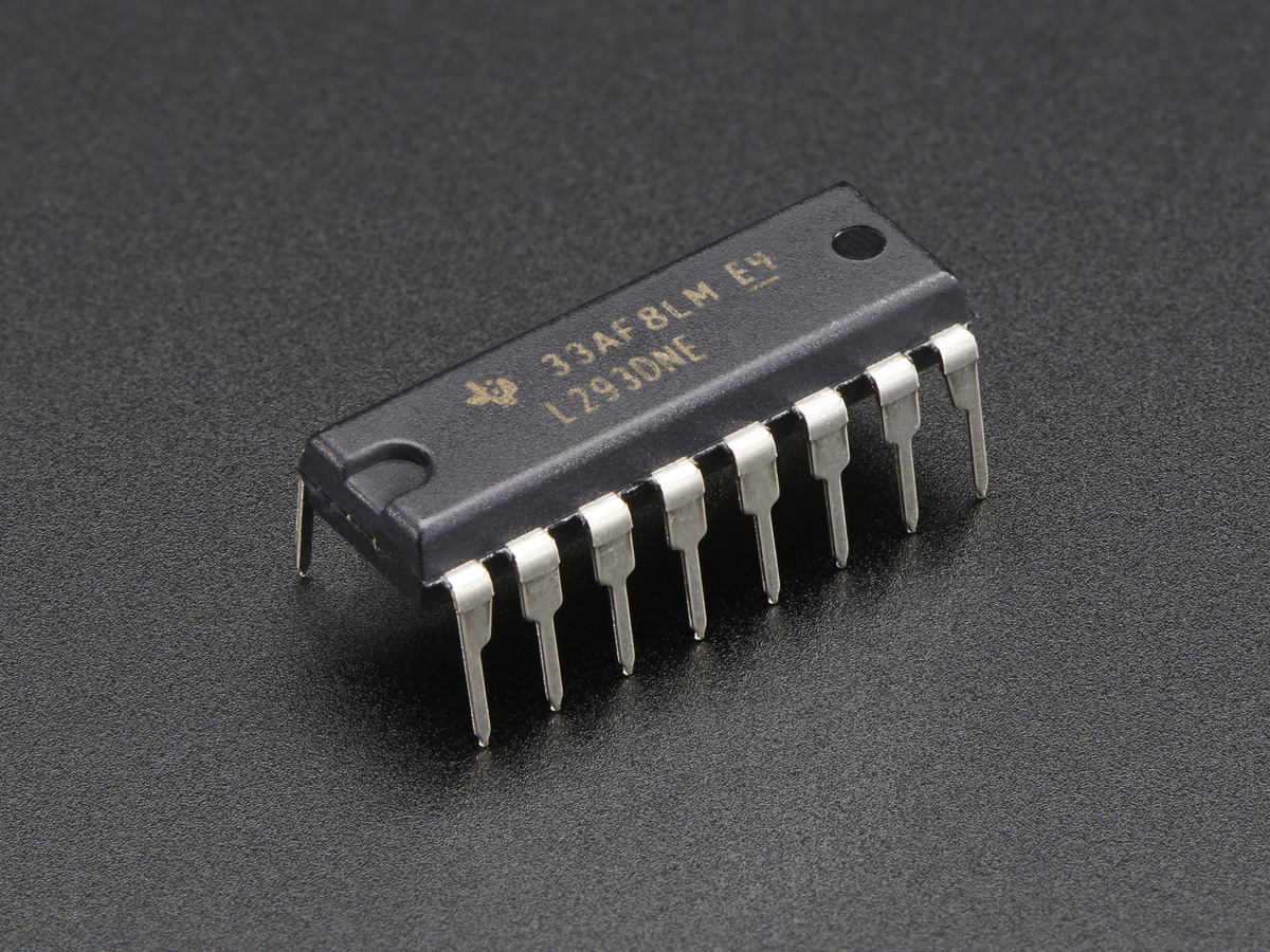
But, as usual, we wanted to learn how does it work and what does it have inside.
A simple H-Bridge can be built with four transistors, four diodes, a motor and a battery.
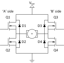
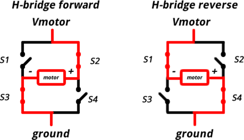
Basically, if Q1 and Q4 (MOSFETs in the schematic but transistors could be used instead) are on, the motor will work in one direction and if Q2 and Q3 are the ones on it will work in the other direction.
But, what happens if you try any of the other possibilities?. In the following table we can see the results of the different possible configurations.
| Q1 | Q2 | Q3 | Q4 | Result |
| 0 | 0 | 0 | 0 | Motor Idle |
| 0 | 1 | 0 | 1 | Motor brakes |
| 1 | 0 | 1 | 0 | Motor brakes |
| 1 | 1 | 0 | 0 | Short Power Supply |
| 0 | 0 | 1 | 1 | Short Power Supply |
| 1 | 1 | 1 | 1 | Short Power Supply |
As we can see, in the first three cases the motor stops either slowly like in the first case, or it brakes like in the other two. In the last three configurations the current will go through the path of least resistance created, probably damaging something in its way.