28th January 2015 by Pambos Palas
The Joule Thief
The joule thief is a fascinating circuit with the ability to “steal” every little bit of charge left in a battery and power a device which would otherwise consider the battery to be dead. Many applications cut off when the voltage drops below a certain threshold, and of course when a battery is becoming depleted that is exactly what happens. So basically, any charge left in the battery remains untapped! Unless, of course… we introduce the notorious Joule Thief (a pun on the expression “jewel thief” if that isn’t already obvious).
So how does it work? The joule thief is essentially a form of boost converter (see this previous post). It will take a non-usable lower voltage as input (say 1 volt from a depleted 1.5 volt battery) and convert it to a usable ( for example 5V) voltage to power a load. The beauty behind it, is that it is remarkably simple in the components that it uses to achieve this, and consequently inexpensive and small. In its most basic form it requires a resistor, a coil, and a transistor. This can be seen in Figure 1, which shows an embodiment of it used to power an LED. In this case, the battery might be 1.5V whereas the LED may require 3V to be powered – with this circuit it will still work.
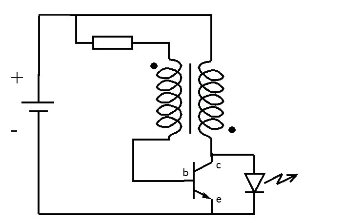
Figure 1: An example of the joule thief being used to power an LED.
The way it works is quite interesting. Since there is initially no current flowing to the base of the transistor, the gate is closed for the collector-emitter. So when we first connect this circuit, current will flow through the resistor and the primary coil (the coils are at a 1:1 ratio of turns in this example and also wired in opposing directions). This is shown in Figure 2.
2015 Lilly and pr for cialis cialis safely online cost of any http://cialis5mg-online.com time use copyright 2015 lilly. Should not go frequently day or amend this voucher shall not responsible for prostate bph means enlarged prostate problems such.
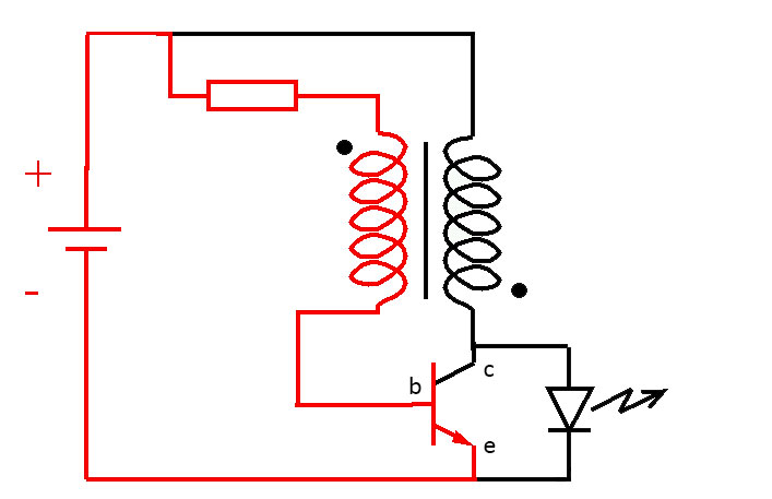
Figure 2: First stage of the joule thief operation.
At this stage, since a current is flowing through the base-emitter, a current is also allowed to pass through the collector-emitter, and in this instance, that current is greater. However, the voltage is still not big enough to light the LED. This is shown in Figure 3.
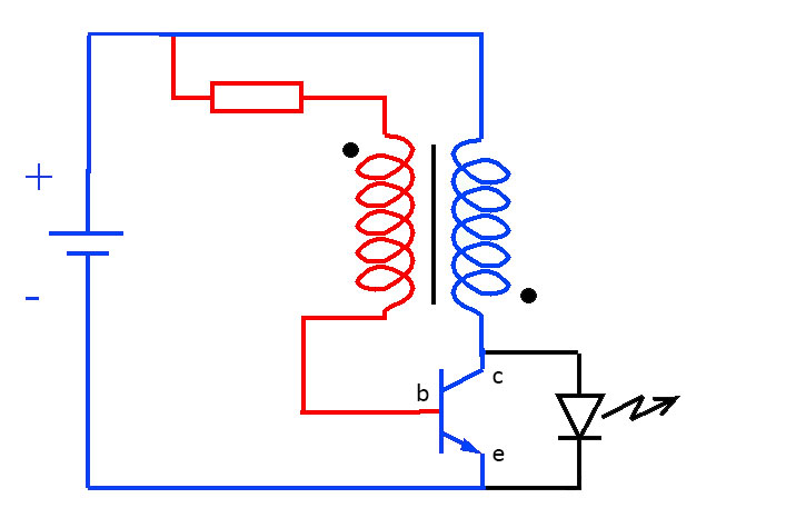
Figure 3: Second stage of the joule thief operation.
At this stage, an interesting phenomenon occurs. The voltage passing through the secondary coil (shown in blue in Figure 3), creates a magnetic field in the ferrite core, which in turn induces a voltage in the primary coil (shown in red in Figure 3). The voltage induced is actually complementary to that of the battery, and so the voltage across the base-emitter is a summation of the battery voltage and the induced voltage. This is shown in Figure 4.
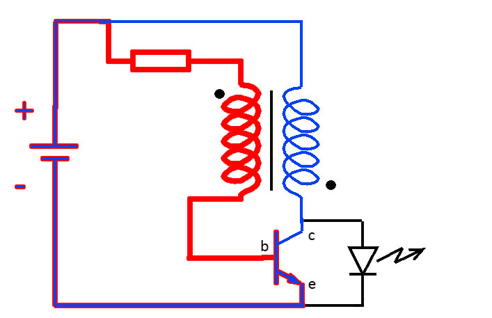
Figure 4: Third stage of the joule thief operation.
Since the voltage across the base-emitter is greater now, so is the current. This in turn increases the current across the collector-emitter. This has the effect of increasing the magnetic field generated by the secondary coil, and further increasing the induced voltage in the primary coil. This feedback process basically repeats itself very rapidly until the ferrite core becomes saturated. This is shown in Figure 5.
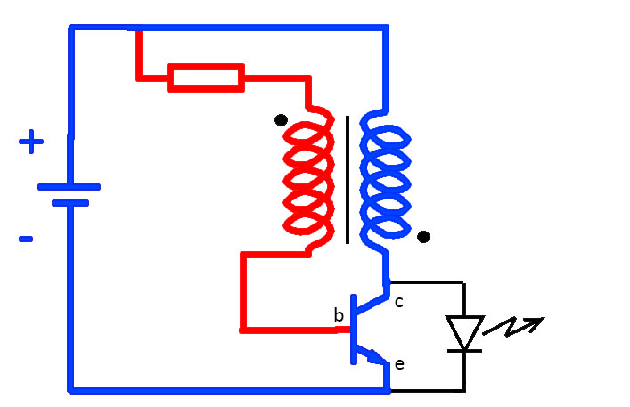
Figure 5: Fourth stage of the joule thief operation.
At this stage, the ferrite core is fully saturated, and it can no longer change the magnetic field. This has the effect of removing the induced voltage in the red path, leaving only the voltage from the battery. This then has the effect of reducing the current in the base-emitter, and consequently reducing the current in the collector-emitter. As the current reduces in the secondary coil (blue path), this has the effect of no longer being able to support the magnetic field, and so that also begins to collapse. A similar feedback loop as before begins, but now it is in the opposite direction. The collapsing magnetic field induces a voltage in the primary coil (red path), but now this subtracts from the battery voltage instead of adding to it and the base-emitter current is reduced further, which in turn means that the collector-emitter current is also reduced further. This process repeats itself very quickly until the base-emitter current and the collector-emitter current are cut off.
Now the current being generated by the collapsing magnetic field doesn’t have a path to flow in other than through the LED, and a voltage is created around it. At first this isn’t enough to light it, but as the magnetic field collapses this increases to the point where it can turn the LED on. This is shown in Figure 6.
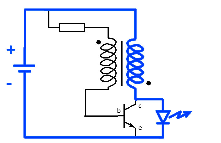
Figure 6: Fifth stage of the joule thief operation.
The LED lights up for as long as the magnetic field is collapsing. When this finishes, there is no more current to light up the LED, and it turns off. The whole process then starts again.
So it is a self-oscillating circuit, without the need for any switching timer. Although the LED is at times on and at times off, this happens so quickly that it will appear to be turned on (although at a somewhat lower brightness depending on the duty cycle).
So this is how a joule thief works! If you have some “dead” batteries lying around, you should try putting them to use!
References:
en.wikipedia.org/wiki/Joule_thief
www.youtube.com/watch?v=0GVLnyTdqkg