15th June 2015 by aegeuana_sjp_admin
How to Build a Binary Clock [PART 1]
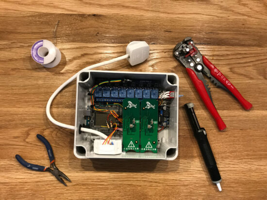
Electronics have always been very interesting for me, but I’ve never had a lot of opportunities and tools to try it. Now, as our office has become more of an electronics lab, I can start to get closer to the electronic part of world.
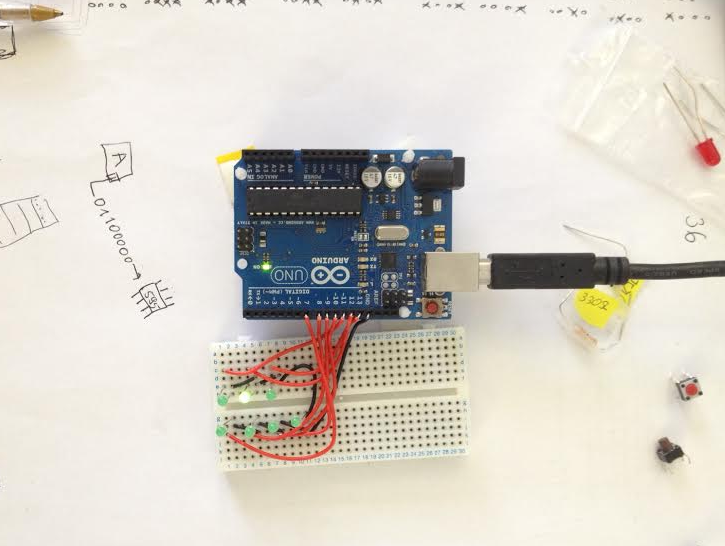
I decided to begin with building a binary clock. It seems to be easy to build and definitely cool to have on my desk. There are a lot of projects online with ready-to-go plans for this kind of thing, however I wanted to learn something new, so I decided to find my own way to create it. The basic prototype was built on an Arduino UNO and the whole concept transferred into a custom built PCB board with an Atmel processor.

How the binary clock works:
Reading the time in binary is fairly easy. Each diode represents a power of 2. The clock has three compartments for hours, minutes and seconds respectively. To read the time you need to add the lit diodes for each compartment.
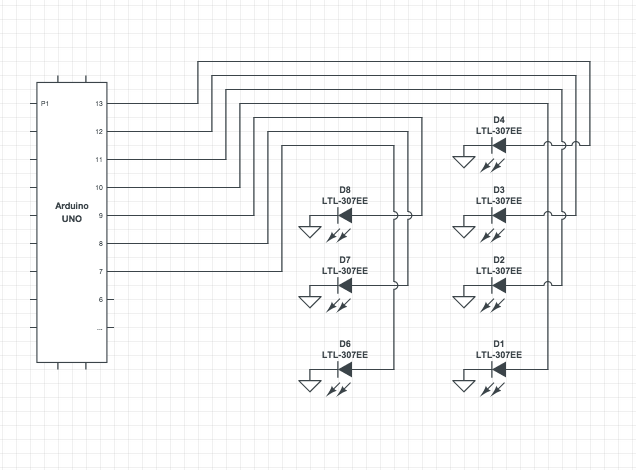
Simple board schematic:
The algorithm:
The first task was to write common functions to turn on and off the right diodes respectively for the decimal value of the time. For that it’s enough to have only the seconds compartment. The algorithm I wrote is built from three basic functions and a few constants:
[code language=”c”]
typedef enum {SEC_1 = 10, SEC_2 = 11, SEC_3 = 12, SEC_4 = 13, SEC_10 = 7, SEC_20 = 8, SEC_30 = 9} SECONDS_MAP; // Map for pins
const uint8_t VALUES_MAP[] = {1, 2, 4, 8}; // Map for powers of 2
[code]
The function to calculate value for particular diodes:
[code language="c"]
void set_pins(uint8_t *pins_list, uint8_t pins_list_size, uint8_t time_part){
uint8_t quotient;
// Specify if diode should be turned on or off
for(int i=pins_list_size – 1; i>=0; –i){
uint8_t val = LOW; // initial value to assign for pin
quotient = time_part / VALUES_MAP[i]; // int division (eg. 2/4 = 0, 3/2 = 1)
if(quotient){ // If quotient greater than 0 set HIGH value for diode and decrease the initial value of time
time_part -= VALUES_MAP[i];
val = HIGH;
}
digitalWrite(pins_list[i], val); // digitalWrite sets value for pin(helper function from Arduino library)
}
}
[/code]
The next function is designed to control separate compartments.
[code language=”c”]
void control_compartment(uint8_t time_part, uint8_t *decimal_pin_numbers, uint8_t *unity_pin_numbers){
uint8_t unity = time_part % 10; // unity part of time (eg. for seconds 56 is number 6)
uint8_t decimal = time_part / 10; // decimal part of time (eg. for seconds 56 is number 5)
set_pins(decimal_pin_numbers, 3, decimal); // Calculate which pins turns on for decimal part
set_pins(unity_pin_numbers, 4, unity); // Calculate which pins turns on for unity part
}
[/code]
Last bit will set up the initial mode of pins and control the whole workflow of the program and will execute in an infinite loop.
[code language=”c”]
void setup() { // setup function is a helper function from Arduino
for(int i=SEC_1; i<=SEC_4; i++){
pinMode(i, OUTPUT); // Set OUTPUT mode for each pin
}
}
void loop() { // loop function is a helper function from Arduino
uint8_t sec = (millis()/1000) % 60; // Just for prototype, take seconds since the program has been running
uint8_t decimal_pins[] = {SEC_10, SEC_20, SEC_30}; // Specify pins for decimal part of seconds
uint8_t unity_pins[] = {SEC_1, SEC_2, SEC_3, SEC_4}; // Specify pins for unity part of seconds
control_compartment(sec, decimal_pins, unity_pins); // Run the control function for compartment
}
[/code]
This was just a prototype to start with. The next step is to move the logic onto a custom PCB without using an Arduino.