19th June 2015 by aegeuana_sjp_admin
How to Build a Binary Clock [PART 2]
When the basic algorithm of turning the diodes on and off is done and tested, it’s time to build the full prototype. This part was completely new for me, as I’d never done anything like it before.
The first step in the process is to design a breadboard with all the necessary components and connections between them.
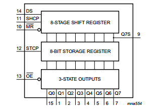
This particular binary clock is based on the Atmel microprocessor Atmega328-PU with 28 pins. 28 pins is not much, but more than enough for a simple clock. In the case where we need more available pins, there is a simple way to increase them. As part of my learning process, I decided to do this by using the `595` shift register, which enables us to split one pin into eight.
The way this component works is fairly straightforward. It receives one byte of data from the microprocessor and checks which bits inside this byte are set, then enables the pins where the respective bits are set to 1.

Once I had enough pins to work with, another problem surfaced – accuracy. The internal microprocessor’s built-in clock is not sufficiently accurate. If we want our clock to be accurate we need to provide an external source for it. This is easy as the microprocessor already has pins prepared to do this.
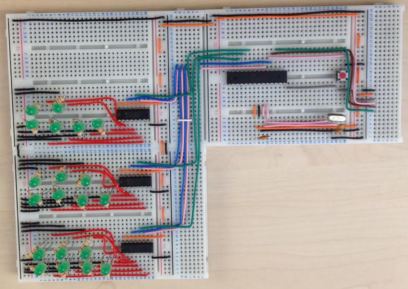
After the whole day of assembly this is the result:

The next step is to program the microprocessor.


