19th December 2015 by Pambos Palas
Step Up (Boost) DC-DC Converters
A common requirement for many applications is the ability to convert the input power. Usually, a device will have a single power input which could be from a battery, directly from mains, or perhaps it will accept a specific voltage or a range of voltages from a Power Supply Unit (PSU). Depending on the complexity of the device however, different components within it will have different voltage requirements and some sort of conversion will be required to make this possible. It would be very common, for example, for the logic ICs to operate on a relatively low voltage (i.e. +5VDC) whereas a motor may require a nominal voltage of +12VDC.
It wouldn’t be practical, or economic, to include a separate dedicated PSU or a separate battery for every voltage level required. Instead, it would make sense to consider the application and choose a voltage that would make sense to use as a base, and then step it up or down accordingly to power peripherals or components that have a different voltage requirement. Depending on power efficiency considerations and heat dissipation, something as simple as a linear voltage regulator could be used to step down a voltage. These come in dedicated ICs, are very cheap, and can guarantee a load regulated voltage.
There are many ways to achieve the same result, and many types of power supplies and voltage regulators. This post will be touching on a Step-Up switching regulator (also known as a Boost Regulator), which is used when the output needs to be higher than the input voltage.
In its simplest form, a boost converted is quite basic in principle. The schematic in Figure 1 below shows the components needed.

Figure 1: Schematic of basic boost converter.
It consists of an inductor (L), some sort of switch (S), a diode (D) and a capacitor (C). The resistor (R) is just the load in this case.
Essentially, this circuit has two states of operation – the “On” state, when the switch is closed, and the “Off” state when it is open. In the former case, as can be seen in Figure two, energy from the input source is stored in the inductor. The load in this case, which is isolated by a diode, is supplied from the capacitor. In the “Off” state, the energy stored in the inductor is added to that of the input source (as they are in series), and together they supply the load current (at a voltage higher than the input source) and charge the capacitor.
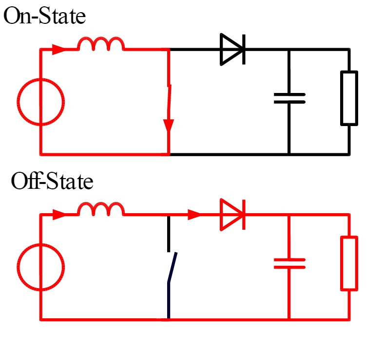
Figure 2: On-Off states of boost converter.
As with most standard circuits, it’s probably not worth building this from scratch. Boost converters are available as single ICs and are very affordable. If you know the specification of what you are trying to achieve (i.e. input voltage, output voltage, maximum current output, desired efficiency etc.), then you can probably find a suitable IC quite easily. This for example is an adjustable boost converter that can go from 1.8V input to 28V output.
Reference
Images – http://en.wikipedia.org/wiki/Boost_converter