17th December 2014 by Pambos Palas
Analogue to Digital Conversion [PART 1 – Signals]
At the heart of modern electronics lies what is known as Analogue to Digital Conversion (ADC). This blog post will cover the general concepts of analogue and digital signals, the fundamentals of ADC and move on to the technicalities of using a Microcontroller Unit (MCU) to perform a conversion. Finally, some sample code will be provided to demonstrate a specific application. No previous knowledge of electronics is assumed for the first few sections, however, the difficulty will increase gradually as we look at the intricacies of ADC and dive into embedded logic.
Analogue vs Digital Signals
If we observe the world around us, we will quickly see that it is largely analogue. What does this mean? Often, when trying to quantify a particular property (i.e. the ambient temperature, someone’s height, the volume of a song that is playing), we find that there are an infinite amount of possible states. The change in state is progressive, meaning that as we heat up some water for example, the temperature of the water will undergo many infinitesimally small changes before it reaches the final temperature, it won’t simply jump degrees! Basically, it is a continuously changing property, and this is the essence of analogue signals. A dictionary definition of “analogue signal” can be: a signal represented by a continuously variable physical quantity.
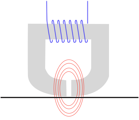
For years, we have used analogue signals in a myriad of applications. One of the more striking ones, for those old enough to remember, is that of tape recorders. Very simply put, an electromagnet applies a magnetic flux to the tape, which permanently changes state and “remembers” the information that was written to it. Looking at Figure 1, we can see how this principle works – an analogue audio signal in the form of a voltage is passed through the blue coil, consequently creating a magnetic flux across the gap of the electromagnet to magnetise the tape. During playback, the exact opposite happens – the motion of the tape creates a varying magnetic field across the gap which creates an electrical signal in the coil. This analogue electrical signal is then amplified and used to drive the speakers.
One of the problems with this technology, and a reason that we shifted towards digital mediums, is that the signal written is not perfectly replicated when read and subject to noise. Although this could be interpreted and converted to a digital signal relatively reliably for some applications (i.e. the magstripe of a credit card), when it comes to music and video, the quality of a good digital signal ensures reliable playback and is clean of noise.
This brings us on to digital signals. Contrary to their analogue counterparts, digital signals do have a finite number of discrete possible states or values. There is no limit on how large the range of possible values is, as long as it is not infinite. A good way of visualising the difference between the two types of signals is by looking at a time graph of each: whereas analogue signals are denoted by a combination of sine waves, digital ones are denoted by square waves due to their discrete (discontinuous) nature.
One of the better-known examples of digital signals is binary data transmission. The only two possible states are 1 and 0, and there is nothing in between. In electronics, binary data would be transmitted with a voltage that varies from HIGH to LOW at a predetermined interval (for example from 5V to 0V). Theoretically, the voltage should be either exactly 5V or exactly 0V, and jump between the two states instantaneously. Of course, in reality this is not the case – even though the signal might be very close to ideal, and might appear so under an oscilloscope, the signal is in fact an analogue voltage that is comprised of multiple sin waves of different frequencies. What is important, however, is that the signal is interpreted as digital: i.e. the device reading it will have thresholds for which it will interpret the voltage as HIGH or LOW. This way, even if a signal has a relatively high amount of noise, it will still be interpreted correctly every time, making digital signals much more reliable and dependable.
The rest of this blog post will focus on the conversion between analogue and digital signals. Click here for Part 2.


