24th December 2015 by Pambos Palas
Strain Gauges [PART 3 – Wheatstone Bridge]
Having covered strain gauges and how they work (see Part 2), it is worth exploring how they are used and how we can get a useful signal from them to represent the strain that a member is undergoing. As discussed in Part 2[link], the property that varies in the strain gauge, as a result of a change of strain, is its electrical resistance.
In practice, strain measurements are in the order of microstrains (1 x 10^-6), and can go up to a few millistrains. Although the strain gauges are sensitive to such small changes, we are left with a further challenge: we need to be able to measure extremely small changes of resistance. As an example, if we look at a strain gauge such as this one [http://uk.rs-online.com/web/p/strain-gauges/0632168/], a strain measurement of 200 microstrains would result in the following change of resistance:
2.1∙(200 ∙10^(-6) ) ∙120Ω=0.0504 Ω
(Gauge Factor x Strain x Strain Gauge Resistance)
So the amount of resistance change that we have to detect is incredibly small, and generally, to measure something like this we would use a Wheatstone Bridge. This has the advantage of allowing us to measure the resistance by measuring an output voltage, but also, depending on our configuration we can offset the effect of temperature sensitivity of the gauge. Following on from the example above, for each degree there is a thermal induced output of 2 microstrains. If the temperature were 10 degrees above ambient, then we would have an error of 20 microstrains on our measurement, which amounts to 10%.
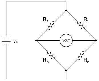
A simple Wheatstone Bridge configuration is shown in Figure 1 below.
There is an excitation voltage of Vin across the bridge, and the output voltage which is measured is defined by the following relationship:

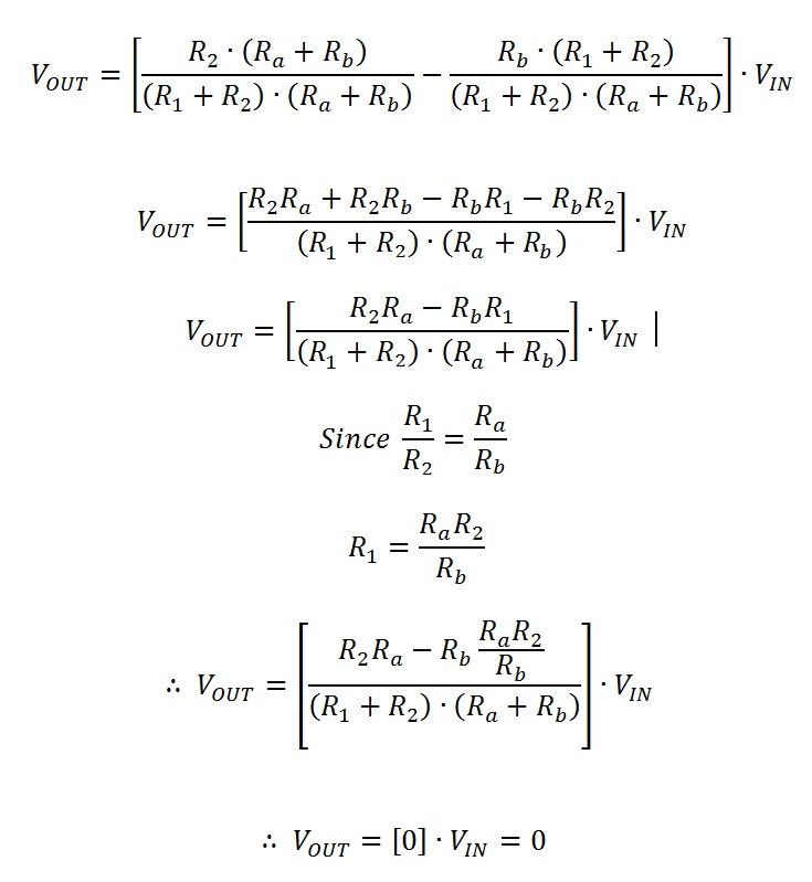
So if the ratio of the two pairs of resistors is equal (i.e. R1/R2 = Ra/Rb), then we can see the following:

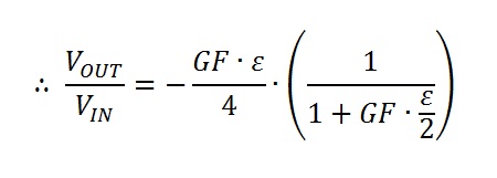
This means that when the ratio of the two resistor pairs is equal, the bridge is said to be balanced, and 0 volts are detected on Vout. Therefore, replacing one of the resistors with a strain gauge will allow us to measure a change in voltage when the resistance changes. The equation describing the change in voltage with relation to strain is as follows:

Where GF is the Gauge Factor.
References:
http://www.ni.com/white-paper/3642/en/
http://en.wikipedia.org/wiki/Strain_gauge


